Friday

Summary: A Personal Experiment & A New Model for Open, Open-source, Anonymous & Secure Wireless Communication
Communication, Network, Protocol Design & Implementation Using Arduino & Raspberry Pi


Updated Nov 23, 2016

Over the course of the last few years, I have been working on a standardized, open-source communication stack that can be scaled from the biggest, most powerful devices, to tiny inexpensive devices like Arduino micro-controllers.

This looks familiar!

In the course of this time, I've made great progress in development of the core RF24 radio driver for nrf24l01+ radio modules. The overall goal of this project is independent of the radio devices, but these devices were chosen due to their relative capabilities vs cost, availability and ease of use. They are simply 2Mbps half-duplex wireless communication devices. Virtually any type of wireless devices can utilize the same theory of operation, including the mesh (RF24Mesh) style protocols.

What is it ? This system/communication stack allows nrf24l01+ radio/wireless devices to be utilized as a standard Network Interface Card (NIC) using TCP/IP & Mesh protocols. This is a summary of the experiment, system, general operation, and some of what I've learned.

Why? The programming, design and implementation of this system is part of a personal experiment I've been conducting involving the nature of wireless communication systems and protocols in relation to privacy, security, the Internet and the Internet of Things.

Theory of Operation & Design:


Consideration A: Open Networks + Anonymity + Automation


In general operation the basic principle of the communication stack is thus:
1. Each device utilizes a unique identifier while connected to a given access point.
2. This 'unique' identifier essentially represents an IP address in this implementation
3. For reasons of simplicity, this implementation also requires a 'static' identifier or IP address, but using more powerful micro-controllers and radio devices, the identifier can be assigned randomly or via DHCP
4. Devices simply attach, at any point in the network, using any available node(s) as an access point.

In a large scale model incorporating this type of design, with proper randomization of identifiers, individual devices and users are (potentially) indistinguishable from one-another initially and generally anonymous.

The next stage of course involves communication to enable the IoT/automation & allowing any capable device to connect. In this case there appear to be some options:

Option A: Leave the network open, and devices can choose to encrypt/authenticate their communications.This may require additional protective measures to prevent abuse in a large or publicly accessible system.

Option B: Assign selected devices a shared "network key" of sorts and incorporate encryption protocols into the network

Either way, it seems that wireless devices & users can inherently maintain their relative anonymity in a system that is designed a little differently.


Consideration B: Mesh Networks

The Network Layer: 
In studying the different layers involved in a capable communication stack, it seemed that many of the boundaries between layers were blurry, with many different systems 'breaking the rules' as it were. A good example of this is TCP/IP which does not strictly adhere to the OSI model.


In my design, a 'static' network architecture is used, which resembles a tree configuration. The simplicity of the RF24Network layer means that each node can handle routing of any type of information, and only needs to know which nodes it is directly connected to. 

Some of the features/functionality involving the RF24Mesh layer have been placed into the RF24Network layer directly. The reasons are mainly due to efficiency and limitations of small devices and this is under review.

Due to the limitations of the specific device used ( nrf24l01+ ) radio modules, each device is limited to 5 individual connections in the mesh, but this could be easily extended for use with more powerful radio devices.

The Mesh Layer:


The mesh layer utilizes its knowledge of the 'static' network architecture to allow individual nodes to attach themselves to the network at any given point where another node is active.

As mentioned above, each device is currently pre-assigned a unique identifier from 0-255 due to the 8-bit nature of very small & low power devices. In a large scale or commercial implementation, these identifiers can be assigned automatically & randomly, with devices then registering themselves in DNS if required, or simply acting as an anonymous client.

The fundamental benefit of a mesh style network is that nodes will automatically adjust their physical address and connection as required as they move around the network or lose connectivity. Any other nodes will provide connectivity by allowing other nodes to attach, and routing or accepting their traffic according to specifications.

Per RF24Network design, there is very little overhead for individual nodes, since they only need to keep track of which node they are connected to, and which nodes are using them as an access point.

Consideration CLimitations

There are currently a number of fundamental imitations and odd 'quirks' that have to be dealt with due to the nature of really small devices like 16Mhz AVR devices.

AVR Devices: The chosen limitations in this case include some of the smallest and least power hungry devices available to any consumer. ATTiny devices can operate as low layer nodes & relays using RF24Mesh, and slightly faster 328 based AVR devices can run an actual IP stack.

uIP TCP/IP Stack:  One of main issues with small devices involves certain limitations of the IP stack. As soon as slightly larger devices are utilized, more robust IP stacks are available that make operation faster and more reliable. uIP has provided a very interesting learning opportunity and is quite amazing given what it can do with extremely limited resources.

Radio Devices: nrf24l01+ radio modules are max 2Mbps half-duplex communication devices with a specific 5-byte addressing scheme.


Consideration D: Fully Automated Networks


Software and wireless development capabilities have come to the point of enabling fully autonomous networks that essentially manage themselves, devoid of human interaction. This goal has been partly realized or demonstrated in theory and action with the RF24Mesh layer, and could easily be built upon and implemented by large scale commercial interests.

The concept of independent networks that configure and maintain themselves may seem to some as a wild idea or a bit of a pipe dream, but we have all of the tools and capabilities within our grasp. It is simply a matter of engineering and development.

Connectivity of individual users can be managed entirely via authenticated and encrypted connections, so there is clearly no need for individual identification of users or user management beyond the application layer.

This type of system could allow communities to simply put up hardware and provide access. The system would be automated to the point that if a device fails, nearby devices send out an alert and the equipment is replaced. That is all.

Consideration E: Wireless Technology and Potential Breakthroughs


Communications technology, aka the Internet, has become ubiquitous in many ways to the daily life of millions and millions of individuals and businesses. Unfortunately, this type of connectivity has not been available to consumers in poor, rural or remote areas in a real, usable way.

Even with existing satellite technologies showing great promise towards providing quality communications capabilities to new places, it seems that additional measures will need to be taken to provide for the age of automation. This is the kind of automation that will see real-time control scenarios, with vehicles communicating among themselves, drawing in information from traffic control systems, news, weather, and countless other systems.  This is the kind of automation that will see drone based grocery and package delivery, combined with, at some point, flying vehicles and high speed transportation systems.

The implementation of automation on a massive scale is going to require something better than the kind of service we get from existing cellular networks and current technology. This is going to require a lot more than what public cellular, 5G and fiber technologies can provide. What we need moving forward is not just a standard step forward in communications technology, but a giant leap forward, while keeping in mind all the things that make the internet and technology beneficial to everybody.


General Summary:

It now seems entirely possible and practical to design and implement fully featured, autonomous. large scale, wireless network architecture that fundamentally provides anonymity and promotes privacy among its users, while providing full mesh networking capabilities and automated network management.

With the emerging nature of communications devices, potential breakthroughs in communication technology, and wireless/IoT/automation technology emerging as a major component of our future progress, it seems very important to study, understand and develop networking and communication technologies with us, the users in mind.

It also seems that wired communications systems have already become a thing of the past, with more and more devices embedding chips and features to support Wireless and WiFi protocols and interfaces. The importance of privacy and security is fundamental to the operation of any large or public communication system, and any large, public & worthwhile communication platform will incorporate these basic ideals as inherent to its operation.


http://nrf24.github.io/RF24Ethernet

http://nrf24.github.io/RF24Gateway


Saturday

New Sampling/Audio library for Arduino : AutoAnalogAudio
Easy access to the internal DAC(or PWM), ADC, Timers & DMA for sound generation

I've been playing around with the Arduino Due for a while now, and finally got to looking over the datasheet and playing around with some of the internals because of ongoing requests regarding audio functionality and advanced timer usage etc.

As a result of my dabbling, I've created a sampling library to simplify access to the onboard Analog-to-Digital (ADC), Digital-to-Analog (DAC), Timer and DMA peripherals.

It is a simplified API that allows users to create a wide range of audio or related applications in short order.

Auto Analog Audio (Automatic DAC, ADC & Timer) library

Goals:
Extremely low-latency digital audio recording, playback, communication and relaying using a simple API

Features:
  • New: Now supports AVR devices (Uno,Nano,Mega,etc)
  • Designed with low-latency radio/wireless communication in mind
  • Very simple user interface/API to Arduino DUE DAC, ADC, Timer and DMA
  • PCM/WAV Audio/Analog Data playback using Arduino Due DAC
  • PCM/WAV Audio/Analog Data recording using Arduino Due ADC
  • Onboard timers drive the DAC & ADC automatically
  • Automatic sample rate/timer adjustment based on rate of user-driven data requests/input
  • Uses DMA (Direct Memory Access) to buffer DAC & ADC data
  • ADC & DAC: 8, 10 or 12-bit sampling
  • Single channel or stereo output
  • Multi-channel ADC sampling
  • AVR devices with no DAC or DMA use pseudo DAC(PWM) & DMA(Timer + Memory Buffer)

Testing:

The results so far have been very good. Using the nrf24l01+ radio modules, I was able to stream a standard format *.wav file of high quality (48khz, 16-bit, Stereo) from a Raspberry Pi to the Arduino Due using a slightly modified version of the included Wireless Speaker example.

To put that in perspective: Data Rate = Sample Rate * Channels * BytesPerSample

Streaming over Radio (RF24):
Data Rate = 48,000 * 2 * 2 = 192.0KB/s 

Streaming from SD Card:
Data Rate = 44,100 * 2 * 1 = 88.2KB/s (maximum rate with noticeable slowdown)

Using an SD card is a bit less exciting, as the audio starts to slow down noticeably with audio of 44.1khz, 8-bit, Stereo. Unfortunately, the SD speed is currently a bit limited, since the HSMCI is not available on stock Arduino Due, and I haven't found a faster working library like sdFat for Due.

SdFat Lib:
The sdFat library works with the due, I just had to initialize it at SPI_DIV6_SPEED (10.25Mhz SPI), and it worked using a value of 5 (17mhz SPI) as well. Initial tests show the max read speeds with the stock SD library at about 113KB/s, and 182KB/s with sdFat lib. Adjusting the SdFatConfig.h file to set ARDUINO_FILE_USES_STREAM = 0 results in speeds of 204KB/s with my current card & module.

These numbers indicate that the Due can handle quite a bit of punishment, and is easily up to the task at hand. The main limitation seems to be the throughput of whatever device is providing the audio or recording it etc.

Initial testing on AVR devices seems to indicate functionality similar to my RF24Audio and TMRpcm libraries.

If using a faster device, or generating audio from tables stored in memory, it seems that the Due with the AAAudio library will most likely handle it.

Notes:

If using the RF24 library in combination with an SD card, I highly recommend using a separate SPI BUS for the radio and SD card. I experienced a number of problems with high speed transfers etc when attempting to extend the length of wires used or connect an SD card module as well.

See the SPI_UART library section of the RF24 docs to enable a secondary SPI BUS for the radio.
Due Pins - TX1: MOSI, RX1: MISO, SDA1: SCK, CS&CE: User selected


Installation: AutoAnalogAudio is available via the Arduino Library Manager


I've also included a number of examples that demonstrate usage:
Click: File -> Examples -> AutoAnalogAudio in the Arduino IDE

SDAudio Examples: Demonstrate how to play back and record WAV/PCM format audio from SD card using the AAAudio library

Wireless Examples: Demonstrate receiving and sending streams of audio data via nrf24l01+ radio modules and are easily modified to work with other radios or devices. Some matching examples and audio samples are included for Raspberry Pi.

Audio Generation Examples: Demonstrate playback of simple audio tones or synthesized audio.

ADC/Audio Capture Examples: Demonstrate how to capture data/audio streams from the ADC on one or more pins/channels.

Documentation: http://tmrh20.github.io/AutoAnalogAudio
Source Code: https://github.com/TMRh20/AutoAnalogAudio

Wednesday

RF24 Addressing: A review of NRF24L01+ radio addressing
Pipes, Addresses and Acknowledegments


There still seems to be a fair bit of questions, misconceptions and misunderstandings regarding the nature of RF24 radio addressing and how to set up communication scenarios. This is a review of RF24 pipes, addressing and acknowledgements that should provide any user with enough information to set up any supported configuration.


Acknowledgements (ACKs):

The radios support an automatic acknowledgement feature, enabled by default, in which the receiving radio switches into transmit mode after reception, and acknowledges reception of data.

1. A sends to B
2. B responds to A
3. A is now aware that B received the payload successfully

The acknowledgment process is very important to understand, because correct addressing is required for this feature to function properly.


Simplest Explanation/Rules of Addressing (Using ESB/Auto-Ack):

1. When using Auto-Ack, every radio can utilize a maximum of 6 unique addresses at once, which other radios can send data to.

2. Each address is assigned to a logical "pipe", and each radio has only 6 pipes that can be assigned addresses.

3. Since auto-ack implies a bi-directional communication channel, each address/pipe can only support communication to a single radio using acknowledgements. If two or more devices send data to a single pipe/address, auto-ack should be disabled to prevent ACK spamming and erroneous acknowledgements.
   Exceptions:
   a: Disabling Auto-Ack - This prevents excessive spamming of acknowledgements and errant acknowledgement.
   b: Timing of Transmissions - Using a token-ring style network or other method of preventing simultaneous transmissions would allow multiple radios to send data to the same pipe/address while maintaining the reliability of acknowledgements.

Note: At 1MBPS, a transmission can take up to 85ms or so, and overlapping transmissions are likely with any significant traffic

4. Per manufacturer design, the addresses assigned to pipes 1-5 must be the same, except for a single byte.


Basic Scenario - One to One Communication with AutoAck:

For purposes of standardization and to allow the system to be scaled, it is generally recommended to use two radio addresses. With auto-ack disabled, a single address can be used for all radios, or groups of radios.


Code:
Radio #1:
byte address_1[] = {0xCC,0xCC,0xCC,0xCC,0xCC};
radio.openReadingPipe(1,address_1);
Radio #2:
byte address_2[] = {0xC3,0xCC,0xCC,0xCC,0xCC};
radio.openReadingPipe(1,address_2);


Process - Radio #1 sending to Radio #2:

1. Radio #1 opens pipe 0 for writing (and internally, reading) using address of Radio #2 (CCCCCCCCC3)
2. Radio #2 receives the data on the first attempt, and (internally) opens a writing pipe using its own address (CCCCCCCCC3) and sends an acknowledgement back to Radio #1
3. Radio #1 receives the ACK, so does not engage in a series of timed retries


Basic Scenario - One to One or Many to Many Communication with Multicast:

With AutoAck disabled, radios can share the same address, and the system can still be scaled to support any number of devices.

Code:
byte address_1[] = {0xCC,0xCC,0xCC,0xCC,0xCC};
radio.setAutoAck(0);
radio.openReadingPipe(1,address_1);

In this situation, any radio can send a message to all other radios sharing the same address:

Code:

radio.stopListening();
radio.openWritingPipe(address_1);
radio.write(&data,sizeof(data));
radio.startListening();


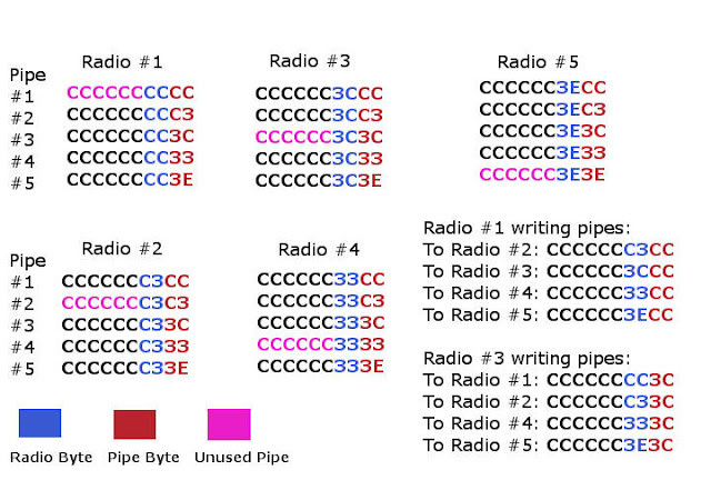
Simple Mesh Scenario - Five-to-Five Communication with AutoAck:


In the above scenario any radio can send or receive data from any other radio in the mesh, thus creating a 'true mesh' of 5 nodes.

Radio #1 will always open a writing pipe using the address assigned to pipe#1 of the recipient.
Radio #2 will always open a writing pipe using the address assigned to pipe#2 of the recipient.
Radio #3 will always open a writing pipe using the address assigned to pipe#3 of the recipient.
... and so on

Process Confusion:
In this example of addressing, if Radio#2 and Radio#3 were to both open a writing pipe to Radio#1 using the same pipe/address, there would be confusion with acknowledgements. Radio#1 will respond to both devices with acknowledgements, since they have both opened a writing and reading pipe using the same address.


Complex Network/Mesh Scenario - Many-to-Many Communication with AutoAck:


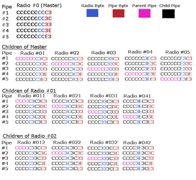
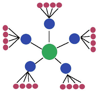
As can be seen, this format of addressing is very similar to creating sub-nets with IPV4 addressing, except here we are using HEX instead of decimals, and there are 5 bytes per address instead of 4. Each radio is linked as shown in the image below, and each radio has a unique communication channel (pipe/address combination) to use when communicating with any of its parent or child nodes.

Due to the correlation of addresses and associated topology, each radio only needs to be aware of its parent and child nodes. Any traffic sent to a given node will either be a: Accepted b: Routed to parent c: Routed to a child

Address configuration, routing etc, can be managed very simply by masking and bit-shifting.


In the above example, pipe0 is NOT assigned a reading address, leaving it available to be used for broadcast or multicast. With AutoAck disabled on a single pipe, or by using selective acknowledgements, all radios or groups of radios can share an address, thus all radios will receive all messages sent to that address.

See the RF24Network Documentation and Source Code for more information regarding this type of configuration.


Summary:

In many low-throughput situations, the radios will appear to function correctly even with improper addressing, and may not cause any obvious problems, however, performance and functionality will most certainly be affected.

In any situation where reliability and acknowledged payloads are important, proper addressing and an understanding of the underlying processes behind acknowledged payloads is very important.


Raspberry Pi/Linux with the nrf24l01+ & RF24Gateway
 A guide/example of advanced RF24/nrf24l01+ usage and monitoring on Linux devices

Overview:

There are many examples of basic RF24 usage, but not so many demonstrating complex communication scenarios and networking. The RF24 communication stack is free, with all development information, examples, code and documentation available on GitHub, designed with Arduino and RaspberryPi/Linux devices in mind.

The RF24 stack generally follows the OSI model, and provides a separate library for each layer, with efforts toward proper documentation for each layer. This allows any type of data/communication to pass over the radios, including TCP, UDP or any other protocol, and users can write their own code to link devices together using any layer(s).

So, what can we really do with these little radios?

The nature and low-cost of the system allows literally anybody with interest in wireless communication to setup, deploy, and experiment with small scale, self-healing wireless networks, or start writing their own code with the core RF24 driver, in a very short period of time.

The stack currently does not include sensor specific code or functionality, it is simply a communication stack which enables all kinds of different functionality.


Requirements, Hardware Setup & Installation:

1. A Raspberry Pi or Linux device a compatible radio device connected
    RPi Install Script

2. An Arduino device with a compatible radio device connected
    Arduino Install (Select RF24, RF24Network, RF24Mesh, RF24Ethernet libraries)

See the RF24 docs for hardware setup info & installation
Note: Please report any issues at https://github.com/TMRh20/RF24/issues

Demonstration and Information:

The video below demonstrates how to use RF24Gateway in general - Setting up nodes and communicating over RF24 using RF24Network, RF24Mesh, and standard protocols (ICMP, HTTP, SSH), along with monitoring

1. Config on RPi & Arduino devices
2. Complex mesh networks: How the different layers (RF24Network,RF24Mesh & RF24Ethernet) can be used with RF24Gateway
3. RF24Ethernet: Simple TCP/IP communication and web server running on Arduino over RF24
4. RF24Mesh: Node config & interaction with RF24Gateway
5. RF24Network: Node config & interaction with RF24Gateway
6. How to use WireShark to monitor user payloads with RF24Gateway and LUA Wireshark dissector script (using laptop w/SSH & X11 forwarding in this example)
7. How to configure Raspberry Pi as a standard node in an existing RF24Mesh
8. How to sniff RF24Network, RF24Mesh, and RF24Ethernet traffic using RF24Gateway & Wireshark(optional)
9. Tacos... oops they were already eaten, maybe next time


As shown in the video, any nodes running RF24Ethernet, RF24Mesh or RF24Network can be used with a master node running RF24Gateway, allowing users to try out or utilize the different layers quite easily.

RF24Ethernet: Provides TCP/IP communication. Very simple and reliable way to control on/off devices via a web browser or scripting. Has all functionality of lower layers.

RF24Mesh: Provides automatic (mesh) networking for RF24Network. RF24Mesh networks are self-healing and dynamic in nature.

RF24Network: Provides addressing, routing, fragmentation/reassembly of payloads via manual/statically defined wireless networks.

See the detailed overview and related pages at http://nrf24.github.io/RF24Ethernet


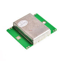
HB-100 / GH1420 10.25GHz Microwave/Doppler Radar Motion Sensor w/Arduino


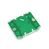
I picked up some of these modules out of curiosity, as these modules can detect the motion and speed of objects through walls or other non-metal obstacles.


Overview:

The modules themselves are fairly simple in use, since they output a signal with the frequency/pulse width indicating the speed, and the amplitude/voltage indicating the strength of the reflected signal.

The speed is very simple to calculate once the frequency of the incoming signal is detected:

km/h = hz / 19.49
mph = hz / 31.36

These HB-100 modules require a pre-amp circuit to boost the IF signal, so I used an LM358N and the circuit at https://hackaday.io/project/371-hb100-radar-shield to boost the intermediate signal.

The output of the circuit sits at about 2.5v when quiet, and moves up & down to represent the received AC waveform.

In pure digital form, this would be very easy to detect using interrupts, but with an amplified analog signal, weaker signals may be missed.

Problem:

Tests with this radar shield using standard frequency counters/libraries seemed to show that interrupts and edge-detection have limited sensitivity to weak signals. They also provide no means for detecting the amplitude of the signal. It seemed that using the on-board ADC may provide better results in this frequency range. (0 to 4000 Hz or 0 to 205km/h)


Goal: 

Detect the frequency and amplitude of low frequency (0-4khz) signals from HB-100 modules, while potentially increasing the sensitivity of waveform detection using the HB-100 & circuit as linked above.

Result:

The resulting code uses the Arduino ADC to sample incoming signals using very simple peak-to-peak detection.

Signals are detected when the waveform transitions above or below a set "midPoint" which represents the 0v value of the AC waveform. Typically, it will be ADC_RESOLUTION / 2.

This is very similar to the edge detection used for interrupts and digital signal detection, but using the ADC to detect weaker transitions.


ADC Resolution / VCC == Volts per Increment ( 1023/5v = 0.005v )
Sensitivity of 10 == peak-to-peak detection of +/- 0.05v signals


Technical Info:

The ADC is driven in free running mode, taking samples at about 38.5khz while looking for specific deviations in the measured voltage that correlate with a peak-to-trough waveform.

The results are summed in a single variable, and returned either as a single result, or an average, depending on how often the results are read in relation to the received signal.

Information about the signal, including frequency, amplitude and number of samples allows more complex analysis.

Conclusion:

The code was developed in a very short time, and can still be considered a work in progress, although it seems good as-is. It tests well up to about 2-4khz with another Arduino producing square wave output. When used with the radar module, it is very sensitive, and allows the sensitivity of the device to be defined in software, and/or results to be filtered.

Code & Examples:

https://github.com/TMRh20/AnalogFrequency


Auto Analog Audio & NRF52840: Now working on non-Mbed cores

 Auto Analog Audio & NRF52840: Now working on non-Mbed cores Playing around with the AAAudio library So I finally decided to make the ne...